
- Home
- Instruments
- Gear
- Recording
- Lessons
- Reviews
- Blog
This article is part of TheGuitarFiles‘s Archive Section which Guitar Fella is slowly trying to rebuild.
I will show you how to replace the old 2 prong power cord to an updated 3 prong with ground on your Vintage Fender Amp. The original 2 prong power cords can be very dangerous, causing you to get shocked, especially in some clubs where the power outlets are not grounded. I’ve personally stepped up to the mic, started to sing, then started to play, and blue flames shot from my mouth. I was using a 69′ Fender bassman head and cab with the old 2 prong power cord. Needless to say this file was written right after I modded it the next day.
First a standard disclaimer: (Caution, Caution, Caution) If you have to ask, you probably shouldn’t be working inside a tube amp. There is in excess of 500VDC in places on a live chassis and if you don’t know exactly what you’re doing, you can Die Really.
A good tech probably will charge around $50 for the job (including parts), so if you’re a little unsure, have it done professionally please.
The following procedure may seem overly complicated, but it’s really necessary since in addition to using an ungrounded 2 wire plug, the old Fenders had the switch on one leg and the fuse on the other.
If the neutral (white) wire were fused, should the fuse blow, you would still have lots of current, only it would travel through the green wire, not the white. Best have both fuse and switch on the hot (black-wire) leg.
Step 1: Purchase a 18g/3 wire cord set (type SJO or SJT) about 8-10 ft long.
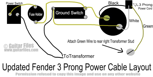
Step 2: Solder a ring-type terminal onto the green wire of the cord set. Get a couple of toothed lock washers of a size which can fit over one of the studs holding the power transformer in place. Tin the exposed ends of the black and white wires. You can also solder the green wire to the ground on the back right rear transformer stud but make sure it’s neat with no cold solder joints!
Step 3: Clip out the old cordset from the “convenience outlet”. Remove all traces of solder and cordset wire from the outlet terminals…you’ll need the entire original inside diameter of the lug free for the rewiring. Don’t try to unscrew the lugs…not necessary nor easy. Use a solder sucker and/or desoldering braid to remove the solder.
Step 4: Remove the old cordset and strain relief by using pliers to compress the longer diameter of the strain relief and pull it out. Save the strain relief you will need it later.
Step 5: Unsolder the white/yellowish jumper from the power switch (leaving one black power transformer primary lead attached to the other terminal). Remove the fuse from the holder and unsolder both leads of the fuse holder. Unsolder all 3 terminals of the ground switch. Keep the wire especially if it’s the nice cotton-wrapped stuff the longer pieces are good to use for the rewiring coming up.
Step 6: Remove the “Death Cap” (.047uF/600V) attached to the wiper of the ground switch lower right side lug. Clip the other end of the cap where it goes through the hole in the chassis. You probably would have a hard time actually desoldering it from the chassis, neatly clipping is ok.
Step 7: Now it’s time to rewire. Starting from the power switch and working toward the AC cordset: Using 20-22g unstranded wire, neatly run a jumper from the unused lug of the power switch (the other lug has one power transformer primary attached) to the “ring” lug of the fuse holder. Keep wire runs neatly tucked inside the lip of the chassis.
Step 8: Run another wire from the tip (innermost) lug of the fuseholder to one upper terminal of the ground switch (probably should be the right-hand side in order to make sure the other black PT primary will be long enough for step 10.)
Step 9: Run still another lead from the ground sw right side lug from step 8 to the lug on the convenience outlet with a brass-colored screw.
Step 10: Attach the other power transformer primary (black) to the left side lug of the grounding switch. Run a jumper from that (left hand) lug to the convenience outlet lug with the silver-colored screw.
Step 11: Strip about 4 inches of the power cordset outer insulation and neatly remove any paper or fiber wrapping. Insert the cordset through its chassis hole and attach the green wire ring terminal over the rear right stud holding the power transformer. Use a lock washer above and below the ring terminal and top it all off with the original nut. Tighten securely.
Optional: If possible, twist the black and white cordset leads and solder the black cordset lead to the convenience outlet terminal with the brass screw, attach the white wire to the silver-screwed terminal. Make sure you don’t have too much exposed wire between the end of the insulation and the solder terminal here it’s really pretty easy to short across to the other 120V leg.
Step 13: Secure the cordset to the chassis with the strain relief. If the new wire is much thicker than the old, you may have to hog out the inside of the strain relief with a rattail file.
Inspect all work, make sure wire ends are neatly clipped and all residue removed from the chassis (it’s all too easy to inadvertently damage the insulation on the existing wiring by slipping with the iron you’ll have to repair any insulation burns with heat-shrink tubing), replace the fuse and speaker, hold your breath and power up.
Important Note: if you follow these instructions, you’ll still have the appearance of the ground switch but it won’t be functioning. This will not be a problem as long as the venue you’re playing is wired to code. Always try to use a 3-prong outlet, and if it ABSOLUTELY HAS to be a 2 prong outlet, use a “cheater” adapter on your cordset and DON’T under ANY circumstance defeat the polarity of the cheater by filing down a prong (note that one prong is wider than the other).

Reader Interactions